
Over the past several years at Abbott Animation, we have been increasingly involved with incident recreation projects. When something goes wrong at a plant or at a refinery — an explosion, a fire, or a chemical release — government investigators or private sector consultants may come to us asking for an incident recreation. These are 3D animations produced with the goal of educating the industry and pushing for stronger adherence to safety standards.
As such, incident recreation has become somewhat of a niche for us, and our efforts at improving our workflows and the quality of our work have often centered around the needs of these projects. Our explosions and dynamics simulations have certainly become more realistic over time, and our library of refinery towers, pipe racks, and equipment grows with every new animation.
Today we will briefly talk about another area that has posed a consistent challenge on many of these projects: Terrain — the landscapes and environments surrounding the places where these incidents have occurred.
For many of our animations we need to re-create real-world environments that represent miles of square footage. Generally, the more extensive a 3D environment is, the less limited you are with respect to camera moves, which is important if we want full creative freedom in the way we compose our shots. Think of how far out into the distance that terrain must stretch in order to reach all the way to the horizon!
With that, let’s walk through Abbott Animation’s terrain generation process via an incident recreation video we recently completed. While manually detailing large-scale terrain is possible, it is far from efficient. The good news is that we don’t have to start from scratch. Since an incident recreation is based on a real-world event, taking place in a real-world location, we can utilize a great resource that is freely available: Elevation data.
We begin by downloading elevation data for the latitude and longitude of the incident location. This elevation data is typically in the form of image files, where values in the image represent the height of the terrain. This data is encoded to higher bit-depths than common file types, such as jpegs, to ensure there is enough precision in the height information and to prevent artifacts in the resulting geometry. You will sometimes hear these elevation files referred to as heightmaps.
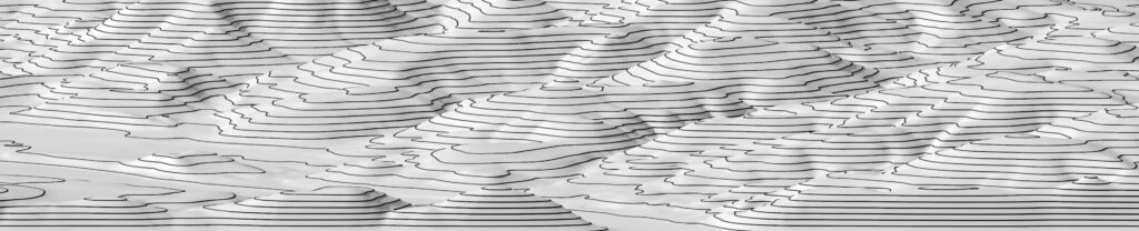
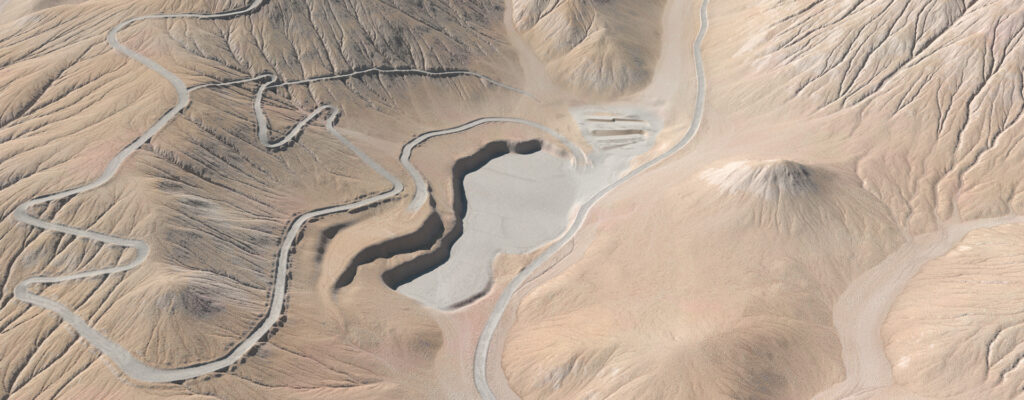
Heightmap files can then be used to displace a type of geometry called a heightfield, which is a very efficient format for representing terrain. Here we see the heightmap data applied to a heightfield grid. This is looking quite promising!
However, once we get closer, we can see that there is a distinct lack of detail. While large-scale terrain features such as hills and valleys are well represented, many small-scale details you might expect to see are missing.
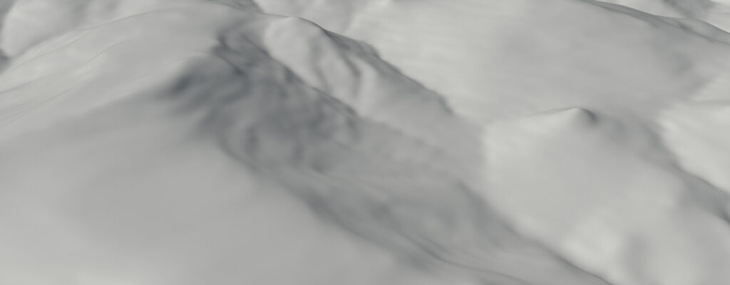
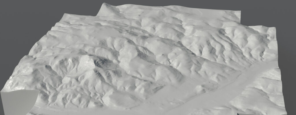
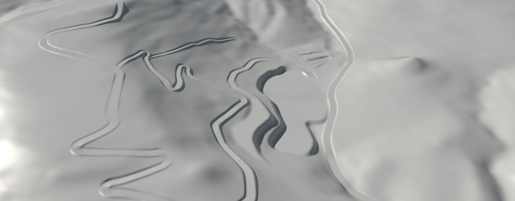
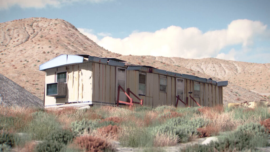
The elevation data unfortunately doesn’t have the resolution to produce terrain suitable for close-up or even medium shots. Another problem is that, in this instance, it lacks the human-built features of the site where this incident took place, namely flattened “terraces” in the side of hills and a large gravel pit area. The elevation data may have been captured before this site was established. This means we need to tweak our terrain a little bit. The desired site features are modeled separately by hand and then overlayed over top of our heightfield. Some parts of this geometry hang over the terrain, while others cut into it.
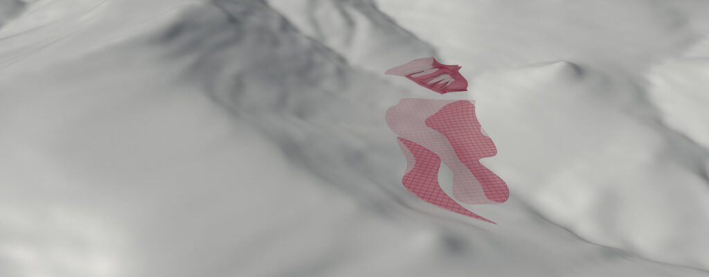
One great feature of heightfields is their ability to take these separate, disjointed pieces of geometry and smoothly integrate them into the terrain, whether it is sitting above or below.
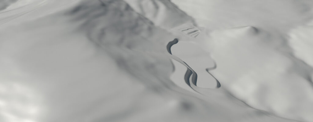
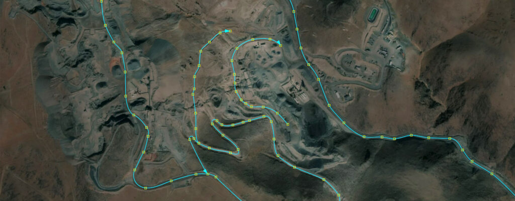
The flattened features we needed are now blended nicely into the hills. However, we are still missing something that was lost in translation due to the fidelity of the elevation data: Roads. To add them back in, we first draw curves representing the missing roads from a top-down view. This is essentially a tracing operation, using satellite imagery of the site overlayed as reference.
These curves are then projected downward where they intersect the heightfield. From here, a surface is extruded along the curve. This surface picks up scale attributes that are present on the control points of our curves, giving us variations in road width.
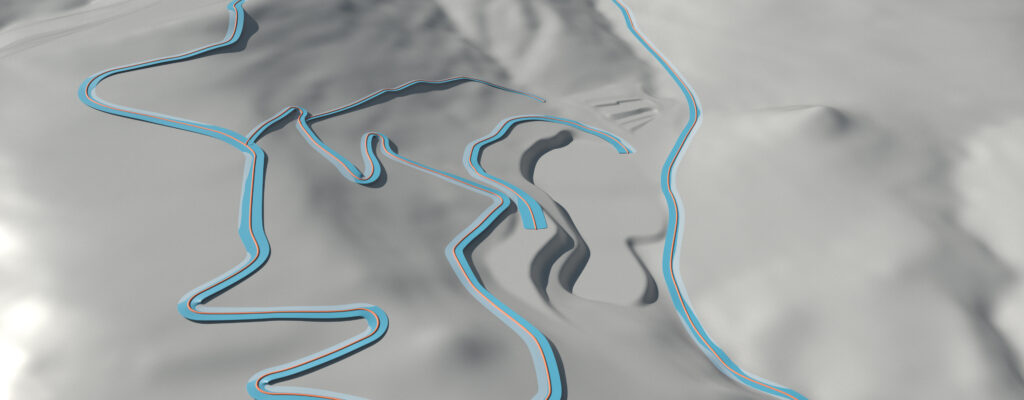
As before, these separate surfaces are now blended into the heightfield. Now we’re getting somewhere.
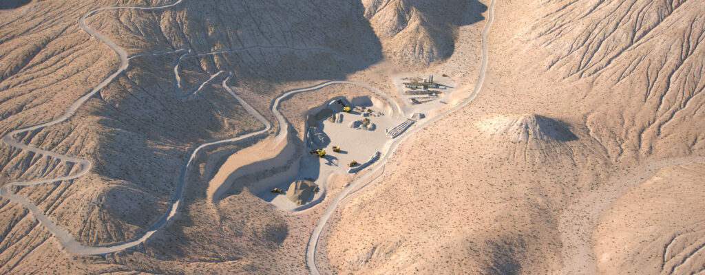
That takes care of the missing site features. But we still don’t have terrain that will work for medium or close-up shots. What we need is some way of injecting detail into the landscape. We could spend a lot of artist time manually sculpting additional detail, but that is cost prohibitive considering the scope of our terrains. Or we could use shading techniques such as displacement mapping and bump mapping, but they have limited effectiveness and won’t produce the desired look without a lot of effort.
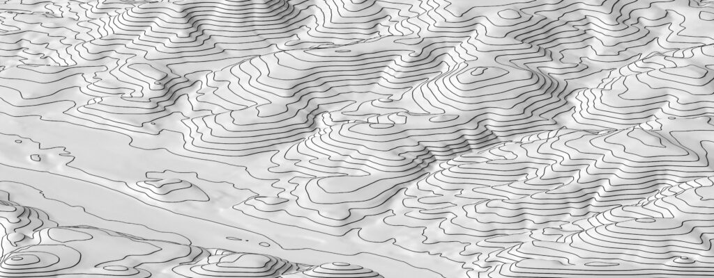
There is however a technique that can be employed to give us the detail we want: Erosion simulations. This technology simulates the natural erosion of rock over time, and in the process, adds a great amount of detail and realism to our heightfield.
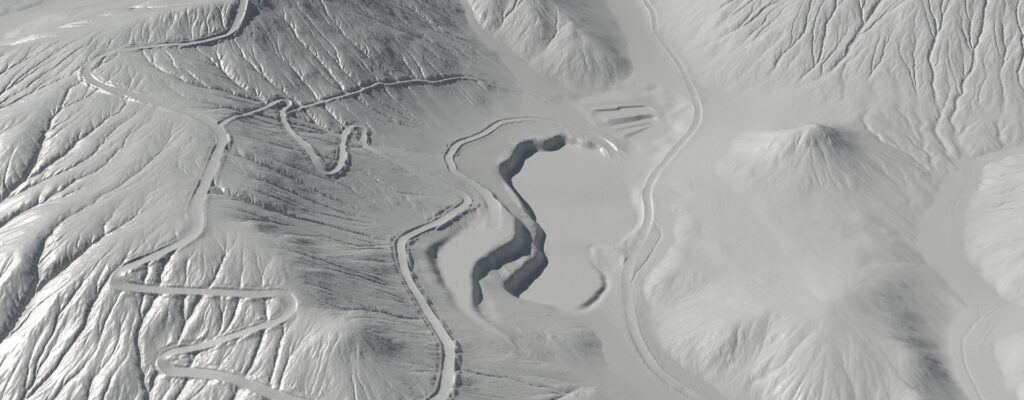
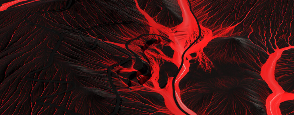
Looking much better now! This simulation process also produces several “masks” that can aid us in the creation of materials for our terrain. For example, these masks can show us where water and debris would collect, or the path of rainwater flowing from the hills to the valleys. Additionally, we can automatically generate our own masks from the features of the eroded heightfield, such as the slope within a certain angle range.
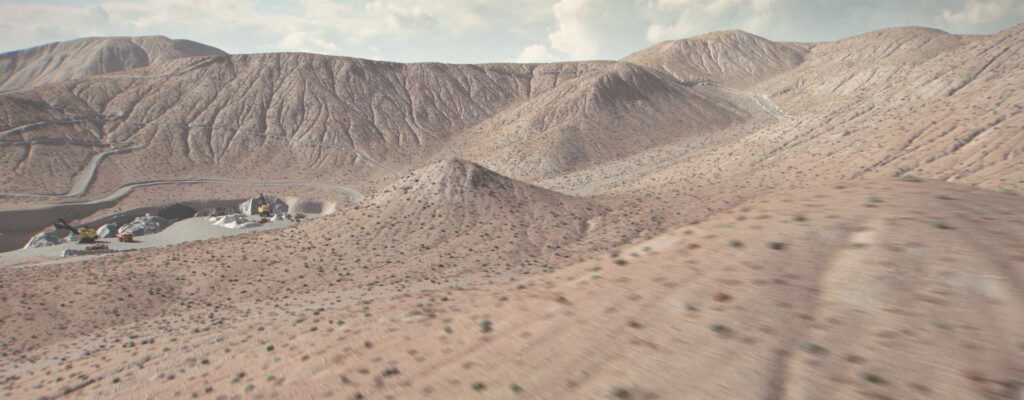
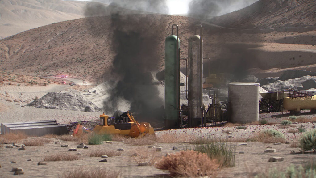
Here we see the terrain with a material applied. This material utilizes several of the masks generated previously to add color variation to the landscape.
And finally, we add the finishing touches: Buildings that dot our terraces, equipment and vehicles, as well as vegetation and rock scatters (a whole topic unto itself!). The rendered layers go through compositing and color-grading to punch up the image and lighting.
And that’s the gist of it! We hope you enjoyed this brief behind-the-scenes look at Abbott Animation’s terrain generation process. Please check out the short animation summarizing the steps below.
Check Out our Creating Large Scale Terrain – Behind The Scenes by clicking the video below!
2 replies on “Generating Large Scale Terrain”
I like your work. Can this be done in any 3d animation software or is it specific to what you use?
Thanks, Dalton!
The techniques described above are intended to be a general guideline and there are methods to achieve each step in all of the 3D animation tools. The steps in this specific example were done using both Maya and Houdini.